Working with Iot One Cloud from Tigase will require you to build circuits in order to add devices. However, without a basic understanding of electricity and circuits, this may become cumbersome. So before we start working with LEDs, sensors and devices let’s go over the basics of constructing circuits and analysis.
One thing to keep in mind is that you will be working with electricity. It is imperative that you take caution while connecting devices and wires! - Ensure that any devices you plug in are unplugged before you change circuits. - Be sure there are no open circuits. - Exercise caution when working with capacitors. - Do not get prototype boards, or devices wet.
An electronic circuit is simply a path for electron flow. It must consist of a source of power, and someplace for that power to go. If there is a gap in that circuit, it’s considered an open circuit and electron flow cannot happen. We will use the positive flow model which will show electron flow from Positive(+) to Negative(-). Also keep in mind that we will generally be dealing with DC or Direct Current. This means that the positive and negative sides of a circuit are discreet and do not change (where as an Alternating Current circuit flips back and forth). This mean the polarity (whether a connection is positive or negative) is especially important while building or diagnosing circuits.
To illustrate this, take a look at the following images.
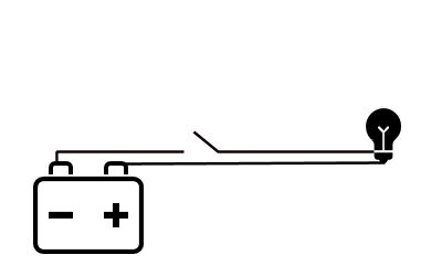
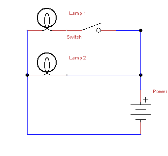
This image shows an open circuit. Without a path for electron flow, the light does not illuminate. The open section can be considered a switch which will close and allow flow.
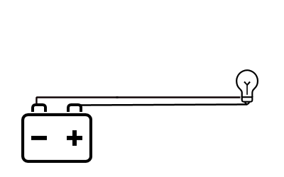
The light is now lit that the path is closed all the way around. This is now considered a closed circuit, electron flow can finish the path from positive to negative.
When talking about electricity, sometimes the simplest analogy is thinking of water moving through a hose. It may not seem to be the most obvious comparison, but it’s the easiest way to explain what each these units mean.
Firstly we have Voltage, this is how many Volts a circuit is running with. Most of our applications use 3.3 or 5V, which on the grand scale of things is not much. Think of volts as the amount of water pressure in the hose, a higher voltage means more pressure.
Next is Amperage, this unit measures the amount of current flowing through the circuit. In the same way, it is the amount of water flow through the hose. Higher currents, or flow, means a higher Amperage. The Raspberry Pi requires at least 500mA (milliamps), or .5A (amps).
Finally is resistance, which as it’s name implies, is how much resistance to electron flow there is in a circuit. Think of this as kinks in the hose. If you’re thinking that a kink in a hose results in an increase in flow, the same rings true in an electric circuit. Resistance is measured in Ohms (Omega).
These three units are all you will need to know in order to build circuits with IoT One Cloud!
Each electrical circuit consists of different components that will do various things to electron flow, or use it to create some result. Although many devices may already be on a board with necessary components, you may find you wish to experiment more with different devices and components, each with it’s own requirements. To prepare you for this, lets go over some of the basic components available to get you better ready for the vast options out there.
Resistors are essentially the kinks in the hose as described above, they provide electrical resistance from one end to the next. Resistors generally do not have a polarity, so it does not matter which way they are pugged in. There are many different types of resistors, but they essentially operate the same.
Resistors are marked with a value that indicates how much resistance it can provide. Some like ceramic disk resistors will have it written on it directly, while barrel type resistors use a color code to indicate the value.
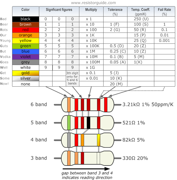
The chart might look a little intimidating, but don’t worry it’s fairly easy to use. To read the resistance, you will need to read from left to right. Although these types of resistors do not indicate which direction they should be read, there is a gap between the bands that places at the most two on one side, that should be on the right where 3 or 4 bands should be on the left. Once you have that, you can start to read the bands. Sometimes it helps to have a pencil handy. The first 2 bands are just digits, so you can write them down based on the color code. If you have a 3 or 4 band resistor, the 3rd band will be a multiplier which multiples the two digits you wrote down. A 4 band resistor will have the last band reserved for tolerance levels, which will say how close to the printed value the resistor should be. The lower the tolerance, the more exact the resistance value should be.
For 5 and 6 band resistors, the first three bands are digits, and the 4th is reserved for the multiplier. The 5th band is reserved for tolerances, just like the 4th band on 4 band resistors. Lastly, 6 band resistors have a Temperature Coefficient value, which lets you know how much the resistance will change during temperature changes. In all likelihood you will not encounter these resistors or need this particular value for our projects.
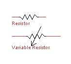
On a circuit diagram they are represented by these symbols:
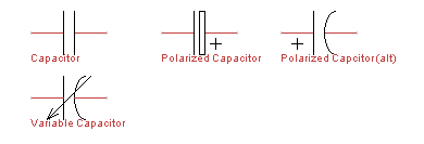
Capacitors allow for the buildup of electrical potential, and then release it when it gets to a set amount. Capacitors can be fixed, in that their capacitance is fixed to a certain number, or variable which can change depending on inputs or physical changes. These are generally polarized, in that it’s important to pay attention to which side goes into a circuit.
Capacitors are generally marked on the outside what their values are.
On a circuit diagram, these are the symbols you will see.
Integrated circuits are what you might think of when you hear the word computer chip. These small black rectangles can perform a variety of tasks depending on their construction. We won’t cover how they work exactly, but there’s a few key things to keep in mind. First, orientation is important. One end of the IC will have a dot, or a small half circle cut out of the plastic material. This indicates the top of the chip, and where you should start numbering your pins. Most ICs come in what’s called a Dual Inline Package, or DIP. The idea is that there’s two rows of pins on either side of the IC. To number the pins, start with the IC oriented with the dot or circle at the top, and start at the top left pin. This is Pin 1, then go down the left side, and then up the right. This can help you identify which pins go where since in a circuit diagram, they may not always be represented the same. Take the below image for example:
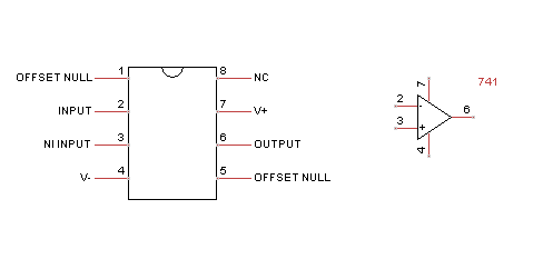
The circuit diagram symbol looks nothing like the IC, but the pins are numbered so you can follow where they are wired!
Light Emitting Diodes have become a popular method of lighting in recent years, and are a common source of illumination in the maker sphere. Whether they are indicators, counters, or just power lights. LEDs are polarized in that electricity can only flow in one direction, this is essentially what a diode does, but in an LEDs case, they give off light as well. When connecting LEds, they might light when connected between power and ground, but it’s not suggested to do this. Since LEDs do not regulate voltage, the diode will pass any voltages through itself and sometimes this can damage an LED. It is recommended you use a small resistor, like a 1k in series when you connect an LED to protect it from burning out (see what series wiring means in the next section). You will also notice that LEDs have a longer and a shorter leg coming from them. The longer leg is the anode, and the shorter is the cathode, which means the anode should be connected to the positive side, and the cathode to the negative side. The circuit diagram symbol is below:
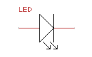
Note that the triangle points to the right, to help indicate the direction of electron flow.
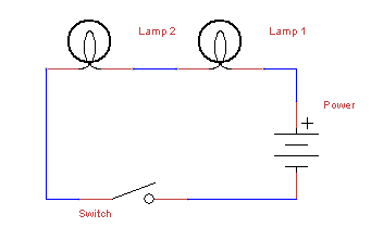
There are two different types of wiring you should be familiar with before building circuits, series wiring, and parallel wiring. They both have different effects on the unit values of a circuit, and they can be employed to do different things. The below example is one of series wiring, where two lamps are wired in series, one after the other. In this example a switch is placed after both lamps, and when the switch is closed, both lamps will be lit at the same time.
Parallel is when two or more paths are available for electron flow as in the following example:
Here electron flow will always go through Lamp 2 as long as power is being applied. Electron flow will only go through Lamp 1 and light it when the switch next to it is closed. This could be used for example to use the lights as indicators: when power is being applied, and when the switch is closed.
Remember that like water, electricity will always go in the path of least resistance, so if you were to put a large resistor in front of one of the lamps, it will effect the behavior of the circuit.
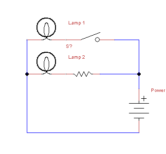
Now, Lamp 1 will be lit when the switch is closed, just like before. But because there is a resistor in front of Lamp 2, it may be dim or go out when Lamp 1 is lit (depending on the value of the resistance). How will we know when if light will go out entirely? We can calculate how large of a resistor we need!
One thing you may need to do is calculate what components you might need to make a circuit work.
The one formula you will need to remember is Ohm’s Law is E=I/R where E = electromagnative force (voltage), I = current (amps), and R = Resistance (ohms). You can of course move these variables around if you need to calculate I or R of the circuit: I = E/R R = I/E
There are some basic principals to constructing a circuit you will need to follow, and depending on which type of circuit you are making, the rules are slightly different. Here are the basics of each circuit type.
- If there is an open part of the circuit, no current will flow.
- Each part of a series circuit has the same current, or amperage.
- The total resistance of a series circuit is the sum of each individual resistor.
- Voltage of the circuit is equal to the sum of all voltage drops.
- Voltage drop across a resistor component is proportional to the size of the resistor.
- If there is an open part of the circuit, current will flow in the remaining parallel paths.
- Each part of a parallel circuit has the same voltage.
- The total current of a parallel circuit is the sum of each individual current between components.
- Total Resistance is calculated using the following formula: 1/Rt = 1/R1 + 1/R2 + 1/R3… This means that the total resistance of a circuit gets smaller with each resistor.
What does all this mean? Well, lets take a circuit and calculate some numbers
The below circuit has two resistors, R1 and R2, each with a resistance of 10 ohms with a 12v power source. If we wanted to know what the voltage is after each resistor, or what the voltage drop is, we can calculate it.
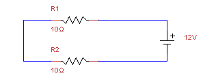
Our total resistance, by the rules stated above in a series circuit is 20 ohms (R1+R2=R). Now we have the E and I of ohms law, we can get the total amperage. I=V/R I = 12/20 I = 0.6 Amps
Now that we know the totals of all the circuits, we can calculate the voltage drop after each resistor, which we will call V1 and V2. V1 = 0.6A x 10 Ohms = 6V V2 = 0.6A x 10 Ohms = 6V
This is important because if you had a component that needed 10V to function, it would not after one of these resistors. Lets see what happens when we change R2 to a larger resistor.
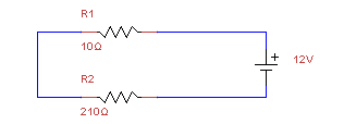
We will need to calculate the total resistance again, which in this case is 15 ohms (R1+R2=R). Our total amperage will be different as well. I=V/R I = 12/210 I = 0.057 Amps
Now for the voltage drops V1 = 0.057A x 10 Ohms = .5V V2 = 0.057A x 210 Ohms = 11.97 V
This parallel circuit has 3 resistors, R1, R2, and R3 with different resistances labeled. We still have a 12v power source.
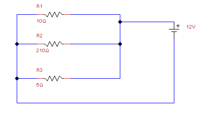
How do we know what current will be on the other side of the resistors? Note that some components can impart some resistance, and may act the same.
First we need to calculate the total resistance of the circuit.
1/Rt = 1/10 + 1/210 + 1/5 1/Rt = 0.1 + 0.005 + 0.2 1/Rt = .305 Rt = 3.28Ω
Since we know what the voltage is across all components, since this is a 12V parallel circuit, we can now calculate the circuit total amperage.
I = E/R
12V / 3.28Ω = 3.67A
Now we have the total current, we can find out what it is flowing to each component:
I1 = 12V / 10Ω = 1.2A I2 = 12V / 210Ω = .057A I3 = 12V / 5Ω = 2.4A
Because we are rounding our figures, I1+I2+I3 is not exactly It, but this is okay since this is well with tolerance levels of devices and components. Lets say now that we have a device that needs 5A to run correctly and we will connect it behind R3, how can you do this?
We can work backwards. Remember we only need three variables, and we have two!
R = 5/12 R = .416
Of course this would be an expensive and hard to find resistor, but you can see how we can calculate what we need.
When making our circuits, we’ll be using breadboards to make working with circuits easy. Here are some considerations to keep in mind while working with them.

As this image shows, the two rows on either side of the breadboard vertically, traditionally used for Positive voltage and Ground are connected vertically. The center holes are connected horizontally, but only for the first 5 holes. The center separates connectivity so DIP ICs can be plugged in down the center. Anything plugged into the adjacent holes will be connected to the pin.