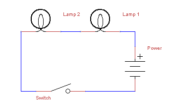
There are two different types of wiring you should be familiar with before building circuits, series wiring, and parallel wiring. They both have different effects on the unit values of a circuit, and they can be employed to do different things. The below example is one of series wiring, where two lamps are wired in series, one after the other. In this example a switch is placed after both lamps, and when the switch is closed, both lamps will be lit at the same time.
Parallel is when two or more paths are available for electron flow as in the following example:
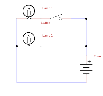
Here electron flow will always go through Lamp 2 as long as power is being applied. Electron flow will only go through Lamp 1 and light it when the switch next to it is closed. This could be used for example to use the lights as indicators: when power is being applied, and when the switch is closed.
Remember that like water, electricity will always go in the path of least resistance, so if you were to put a large resistor in front of one of the lamps, it will effect the behavior of the circuit.
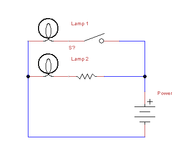
Now, Lamp 1 will be lit when the switch is closed, just like before. But because there is a resistor in front of Lamp 2, it may be dim or go out when Lamp 1 is lit (depending on the value of the resistance). How will we know when if light will go out entirely? We can calculate how large of a resistor we need!
